Parallelization of a microirrigation simulation
The problem
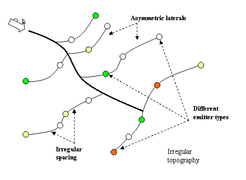
This work presents the necessary gridable equations to simulate the hydraulic behavior of an open pipe network while minimizing physical and mathematical simplifications. A general case of an open hydraulic network is shown in figure 2. Note that for this network the following conditions apply:
-
Irregular topography
-
Mixed emitter type
-
Heterogeneous laterals
-
Irregular spacing between emitters and laterals
-
Irregular pipe diameters.

Figure 2. Characteristics of an open pipe network.
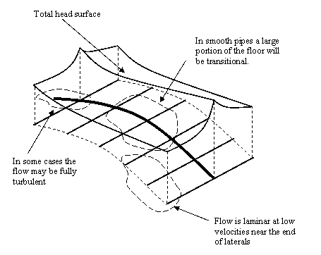
Figure 3 shows the total head distribution in a system with homogeneous laterals and equally spaced emitters.

Figure 3: Flow Regimes in Microirrigation.
Generally, the Reynolds number increases from the last outlet towards the entrance of the manifold. A rigorous approach to determining the distribution of head, flow rates and discharges requires that the Bernoulli equation be applied between the entrance of the unit and each emitter, and that the continuity equation be applied at each node. This approach has two problems. First, a large number of non-linear equations result from this approach. Second, the points at which the critical flow and the change from transitional flow to turbulent flow occur are not known. These problems led to the classical assumption that emitter discharge is constant. Thus, mean velocity, Reynolds, and f are known. This assumption has proven to be adequate when pressure variations are maintained within a relatively small interval. However, under steep, varying slopes this assumption does not hold.
Parallelized Solution using characteristic curves
An alternate solution to the problem of determining the pressure, flow and discharges within the network is based on knowledge of the characteristic curves of system components that control flow rate (the emitter, lateral and manifold).
The characteristic curve of the emitter is known.
![]() (8)
(8)
Knowledge of the geometry and the hydraulic characteristics of the lateral allow calculation of the characteristic curve of the lateral, which can be represented as:
![]() (9)
(9)
Similarly, the equation for the manifold can be represented as:
![]() (10)
(10)
Characteristic curves of the laterals and manifold
The characteristic curve of the lateral is the relationship between head at the entrance of the lateral and the flow rate entering the lateral. A point of the characteristic curve of a lateral can be calculated by assuming a pressure at the last emitter and calculating flows, discharges and heads for each upstream section until the entrance of the lateral is reached.
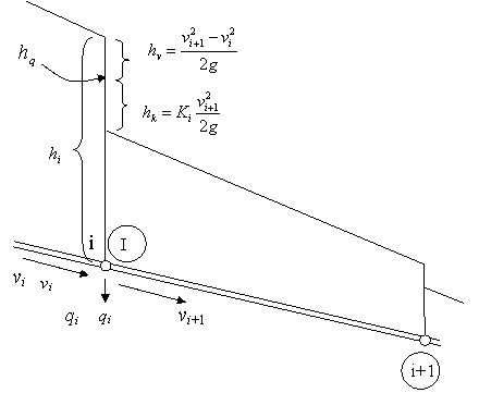
Given the pressure at the last emitter the discharge at the last emitter can be calculated. The continuity equation can then be used to determine the flow rate in the pipe section upstream of the emitter. Then, apply Bernoulli between the emitter and the next upstream emitter (figure 4) to obtain the pressure at the upstream emitter. This process can be repeated until the entrance of the lateral is reached.

Figure 4: Definition of elements used in the calculations.
The working equations are:
![]() (11)
(11)
![]() (12)
(12)
 (13)
(13)
and equations (3), (4) and the equations in Table 1.
Repeating the process for different values of the end pressure, the characteristic behavior of the lateral can be expressed in tabular form. If desired, the coefficients C1 and x1 for equation 10 can be obtained by linear regression.
The same analysis can be conducted for the manifold, using the lateral characteristic curves to determine the discharge into the lateral.
Head, flow rate and pressure distribution
Once the characteristic curves of the manifold, laterals and emitters are known, given a pressure at the entrance of the manifold, the system’s pressure, flow rate and discharge distribution can to be calculated using the following recurring sequence:
- Using the manifold characteristic curve calculate flow into the manifold.
- Establish Bernoulli’s equation between the entrance and the first lateral to determine the pressure at the entrance of the first lateral.
- Calculate the flow into the lateral(s) using the corresponding lateral characteristic curve.
- Using the principle of continuity, calculate the flow in the downstream pipe section.
Repeating this process the flow rate and pressure distribution can be calculated along the manifold. Since the flow rate and pressure distribution is known along the manifold, the same procedure can then be applied to each lateral to obtain the pressure, flow rate and discharge distribution over the system.
The working equations are:
 (13)
(13)
and equations (3), (4), (5), (8), (9) and (10), and the equations in table 1.